Az önfúró- és önmetsző csavarok peremtávolsága
Önfúrócsavar – útmutató 4. rész
Az önfúró- és önmetsző csavarok peremtávolsága
Az önfúrócsavar útmutató előző részeiben a csavarok különböző típusaival, különböző fejformákkal és behajtási módokkal, valamint az önfúró csavarok gyártási folyamataival foglalkoztunk.A mostani rész az önfúró csavarok fa, acél és alumínium építőelemekbe történő rögzítésekor betartandó peremtávolságokkal foglalkozik.
A megfelelő peremtávolságoknak köszönhetően kevesebb a hibalehetőség
Az önfúró és önmetsző csavarok különféle alkalmazási területeken használhatók. A fő alkalmazási terület a profilozott acél- és alumíniumlemezek, valamint a szendvicselemek csavarozása az ipari könnyűszerkezetes tető- és falfelületeken. Az említett építőelemek alapszerkezetei többnyire vékonyfalú, hidegen formázott acélból és alumíniumból, valamint fából készült építőelemek.A kivitelezés követelményeit és méretezését a műszaki szabványok és engedélyek szabályozzák. A rögzítőelemek használatakor fontos szempont az alkatrészek szükséges peremtávolságainak betartása. A fa építőelemek hiányosságai, valamint a lemezen lévő hosszúkás lyukak és repedések miatti meghibásodások ily módon megelőzhetők.
Hol találok információt a szükséges peremtávolságokról?
Az alkatrészek méretezésére vonatkozó információkat a szabványok tartalmazzák. Az anyag típusától függően különböző szabványokat használhatunk.Faelemek
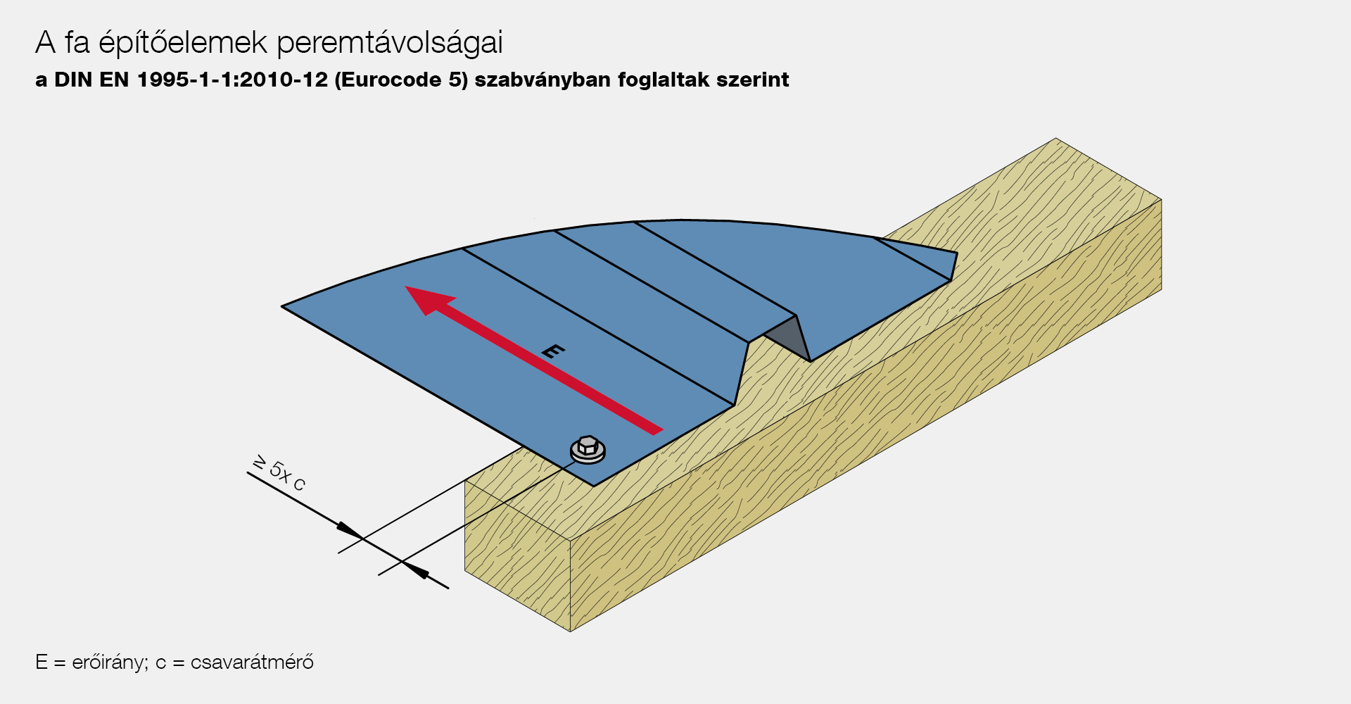
A fa építőelemek peremtávolságairól például a DIN EN 1995-1-1:2010-12 (Eurocode 5) szabványban találunk információkat.Számos paramétert kell figyelembe venni, amelyek befolyásolják a szükséges peremtávolságot:
- A fa száliránya
- Az erő és szálirány közötti szög
- Igényelt / nem igényelt perem
- A csavar átmérője
- Kivitelezés előfúrt / nem előfúrt csavarokkal
Az EJOT JF valamint JT típusú csavarok a peremtávolság kiszámításakor alapvetően előfúrtnak számítanak. Az egyetlen kivétel a JA típus, ezeket a csavarokat elő kell fúrni (0,7 xd). Ezért a számításnál csak a minimális távolságokat előfúrt lyukakkal kell figyelembe venni a DIN EN 1995-1-1:2010-12 szabvány szerint.
A DIN EN 1995-1-1:2010-12 szabvány részletes táblázatai és ábrázolásai egyértelművé teszik, hogy a szükséges peremtávolságot nem lehet a faépítésre vonatkozó szabványok speciális ismerete nélkül meghatározni.
Amennyiben kérdései vannak a szükséges peremtávolságok helyes kiszámításával kapcsolatban, az EJOT készséggel áll rendelkezésére.
Acél- és alumínium építőelemek
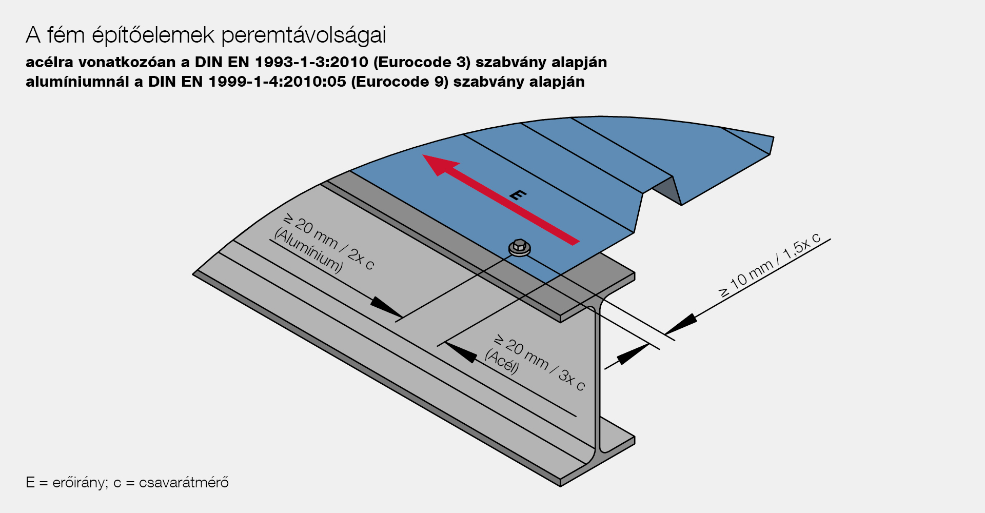
Az acél és alumínium szerkezetek használatakor egyszerűbb a peremtávolságok meghatározása. A DIN EN 1993-1-3:2010 (Eurocode 3) szabvány szabályozza a vékonyfalú acél alkatrészek peremtávolságát. A következő paramétereket kell figyelembe venni:
- Csavarátmérő
- Erőirány
A DIN EN 1993-1-3:2010 szabványban található táblázatok és diagrammok segítenek a helyes peremtávolság kiszámításában.
Hasonlóan egyszerű a dolgunk a vékonyfalú alumínium szerkezeteknél. Itt a DIN EN 1999-1-4:2010:05 (Eurocode 9) szabványban egy ábrában összefoglalva megtalálja a leírást.
Hasonlóan egyszerű a dolgunk a vékonyfalú alumínium szerkezeteknél. Itt a DIN EN 1999-1-4:2010:05 (Eurocode 9) szabványban egy ábrában összefoglalva megtalálja a leírást.


